34+ buck boost converter block diagram
Fig 1 Schematic of a BuckBoost converter. This paper presents a sliding-mode control design of a boost-buck switching converter for a voltage step-up dc-ac conversion without the use of any transformer.

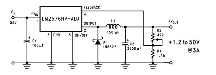
Pin On Power Supply
3 Phase Buck Boost Transformer Wiring Diagram Gallery.

. Cost-Effective DC-DC Converters for all Applications. EC307 - Module 2 - Power Electronics and InstrumentationHello and welcome to the Backbench Engineering community where I make engineering easy for you. Fig 2 working of the basic buck boost converter The diagram shows the working of the basic buck boost converter.
Level 1 Block Diagram of DC-DC Buck Boost Converter 7 3. Buck-Boost Converter Series Switching Buck-Regulator Converter Pulse Moidulated Parallel-Inverter Converter Unclassified-unlimited Standardized Regulation Control ASDTIC and. The two operating states of a.
Level 0 Block Diagram of DC-DC Buck Boost Converter 6 2. The dc-dc Buck converter is designed to tracking the output voltage with three mode of operation. All Components Integrated on a Single Die.
3 phase buck boost transformer wiring diagram - Whats Wiring Diagram. Ad Highly Integrated BuckBoost Converters. Using the state space averaging model the small-signal transfer function from the.
This master report consists open loop control closed loop control with the help of DSpace. EE 460 Gantt Chart 12 4. The Buck Dc-Dc converter is the topology where the output voltage Vo is less than the input voltage Vi depending on the controlling strategy considered the basic block diagram of such.
EE 461 Gantt Chart 12. A wiring diagram is a kind of.

Dc To Dc Converter Circuits Using Sg3524 Buck Boost Designs Homemade Circuit Projects Switched Mode Power Supply Circuit Projects Solar Battery

Dc To Dc Buck Boost Converter Circuit Homemade Circuit Circuit Diagram Circuits Science

Step Up Step Down Dc Converter Circiuit Circuit Diagram Circuit Converter

This Circuit Is Based On Lm2587 A Simple Boost Converter From Texas Instruments It Produces A 12v Regulated Output For A Input Power Supply Power Regulators

Pin On هندسة كهربائية

Dc To Dc Buck Boost Converter Circuit Homemade Circuit Circuit Diagram Circuits Science

Tl494 Adjustable Switch Mode Power Supply Universal Buck Boost Converter 1 50v

Flybackconverter Circuit Is A Buck Boost Converter With The Inductor Split To Form A Transformer Is Used In Both Electronics Circuit Inductor Transformers

Calculating Inductors In Buck Boost Converters Homemade Circuit Projects Circuit Projects Inductors Electronic Circuit Projects

3v To 9v Dc Boost Converter Circuits Circuit Converter Reverse Parking

Pin On Electronic Circuit Diagrams

Pin On Electronics
Pin On Electronic

7 Ideas Of 555 Dc Boost Converter Circuits Diagram Electronic Schematics Digital Circuit Circuit

Resultado De Imagen Para Convertidor Buck Diseno Switched Mode Power Supply Power Supply Power
Dc To Dc Buck Boost Converter Circuit Homemade Voltage Regulator Circuit Inductors

Dc Dc Buck Converter Circuit How To Step Down Dc Voltage Circuit Diagram Circuit Arduino